46~83 item / All 83 items
Displayed results

Added to bookmarks
Bookmarks listBookmark has been removed
Bookmarks listYou can't add any more bookmarks
By registering as a member, you can increase the number of bookmarks you can save and organize them with labels.
Free membership registration
46~83 item / All 83 items
This is a specially designed small wind tunnel to visualize the airflow around a model. The compact device can be demonstrated in various locations, such as classrooms, regardless of the laboratory setting, and can be easily moved and stored when not in use. The airflow moves from the bottom to the top. Air entering from the bottom of the device passes through a converging section and a comb-shaped nozzle, then enters observation ducts illuminated on both sides. The lighting clarifies the streamlines around the model. There is a variable-speed fan at the duct exit, which adjusts the flow rate based on volume. A smoke generator is located at the bottom of the device. Smoke (oil droplets) is produced by heated vegetable oil and carbon dioxide supplied from a cylinder, and is sent to the comb-shaped nozzle. From the comb-shaped nozzle, 23 streamlines are released to observe the airflow around the model.
Added to bookmarks
Bookmarks listBookmark has been removed
Bookmarks listYou can't add any more bookmarks
By registering as a member, you can increase the number of bookmarks you can save and organize them with labels.
Free membership registration
This open-type suction wind tunnel can conduct a wide range of experiments related to fluid dynamics while being compactly designed. It consists of a large bell mouth, a two-dimensional nozzle contraction body, an experimental area (305x305x600mm), a diffusion body, a protective mesh, an axial flow fan, and a silencer unit, achieving a flow with minimal turbulence. The control unit (desktop type) regulates the rotational speed of the axial flow fan and controls the flow velocity in the experimental area. The wind tunnel and control unit mounted on a caster-equipped frame are designed to be very compact, making it easy to change their arrangement. Various options can be added according to the experimental purpose. The optional data automatic collection system VDAS (sold separately) can display measurement data in real-time on a computer (sold separately) and can calculate and graph the collected data, facilitating a smooth progression of experiments.
Added to bookmarks
Bookmarks listBookmark has been removed
Bookmarks listYou can't add any more bookmarks
By registering as a member, you can increase the number of bookmarks you can save and organize them with labels.
Free membership registration
This open-type suction wind tunnel, despite its compact design, allows for a wide range of experiments related to fluid dynamics. It consists of a large bell mouth with a honeycomb, a two-dimensional converging nozzle, an experimental area (125x125mm), a diffusion section, a protective mesh, a variable-speed fan, and a silencer unit, achieving a flow with minimal turbulence. The included manometers (6 units) and two Pitot tubes positioned before and after the experimental area measure wind speed and the pressure distribution in the wake of the model. The experimental area has four sides made of transparent acrylic panels, with the front and back panels being removable. The device comes with a single force balance measurement system and three types of experimental models (a cylindrical model with pressure holes, a NACA0012 wing model, and a flat plate model), allowing for immediate experiments on drag or lift, as well as pressure distribution experiments around a cylinder. The drag or lift (N) is digitally displayed on the included display unit. Additionally, the single force balance measurement system can be mounted on the underside of the experimental area, enabling the measurement of drag (N) with original test specimens made using a 3D printer or similar methods.
Added to bookmarks
Bookmarks listBookmark has been removed
Bookmarks listYou can't add any more bookmarks
By registering as a member, you can increase the number of bookmarks you can save and organize them with labels.
Free membership registration
The open channel is a variable slope type with a width of 300mm and a depth of 450mm, and the length of the channel can be selected from 5/7.5/10/12.5/15M. The channel consists of a water storage tank, a water circulation pump, a flow meter, a channel slope adjustment device, an electric drainage gate, and a control panel. The channel is equipped with a digital flow meter and an inclinometer, and a separate control panel manages the water flow, channel slope, and drainage gate level, with the drainage gate level setting the water depth in the channel. Pressure measurement holes spaced 25cm apart along the channel allow for analysis by connecting to a separately sold manometer or pressure display. The FC300 comes with necessary equipment for experiments, including a sluice gate, a weir, a depth gauge, a pitot tube for total pressure measurement, and a float switch, along with an experimental manual. Additionally, various options (sold separately) are available to suit experimental purposes. Furthermore, the included dedicated software (VDAS) can display and save water flow and channel slope data in real-time to a PC (sold separately).
Added to bookmarks
Bookmarks listBookmark has been removed
Bookmarks listYou can't add any more bookmarks
By registering as a member, you can increase the number of bookmarks you can save and organize them with labels.
Free membership registration
A transparent container that creates various types of vortices, generating natural and forced vortices, and measuring their shapes and movements. The device consists of a transparent container with a diameter of 380 mm that rotates with a variable speed motor, a removable perforated transparent container with a diameter of 286 mm, and a traversing pitot tube and depth gauge. Experiments will be conducted with the natural vortex flow using the perforated transparent container attached, and with the forced vortex flow after removing it.
Added to bookmarks
Bookmarks listBookmark has been removed
Bookmarks listYou can't add any more bookmarks
By registering as a member, you can increase the number of bookmarks you can save and organize them with labels.
Free membership registration
We observe the impact of a precise and rapid high-speed jet stream on the test specimen (blade) and measure its force. As an optional accessory, a 120° conical plate and a 30° inclined plate (H8a) are also available, allowing us to measure the forces on various surfaces subjected to jet impact and understand the laws of momentum to solve jet impact problems.
Added to bookmarks
Bookmarks listBookmark has been removed
Bookmarks listYou can't add any more bookmarks
By registering as a member, you can increase the number of bookmarks you can save and organize them with labels.
Free membership registration
The analysis of the flow through the orifice will be conducted as a function of cross-sectional area, flow velocity, and flow rate. It consists of a cylindrical glass tank and an orifice, allowing observation of the water head situation through the orifice, and the measurement of the water head and its range of the jet flow using an integral pitot tube. An aluminum orifice set (6 types) is included. A H1F hydraulic bench (sold separately) is required for water supply and flow measurement for the experiment.
Added to bookmarks
Bookmarks listBookmark has been removed
Bookmarks listYou can't add any more bookmarks
By registering as a member, you can increase the number of bookmarks you can save and organize them with labels.
Free membership registration
This is a portable small water channel consisting of a 2.5M long transparent acrylic water channel and slope system. It is designed to be used in combination with the hydraulic bench H1F (sold separately), and comes with necessary weirs, flumes, depth gauges, and pitot tubes for total pressure measurement, along with the experimental procedure manual.
Added to bookmarks
Bookmarks listBookmark has been removed
Bookmarks listYou can't add any more bookmarks
By registering as a member, you can increase the number of bookmarks you can save and organize them with labels.
Free membership registration
It is a small water channel made of reinforced plastic, which allows for the installation of different weirs to control the flow and measure and analyze the flow rate. The device is installed on a hydraulic bench H1F (sold separately) to supply water. It comes with a rectangular weir, two types of V-shaped weirs, and a height gauge. For the experiment, a hydraulic bench H1F (sold separately) for water supply and flow measurement is required.
Added to bookmarks
Bookmarks listBookmark has been removed
Bookmarks listYou can't add any more bookmarks
By registering as a member, you can increase the number of bookmarks you can save and organize them with labels.
Free membership registration
It consists of a 2.5M long adjustable slope open channel, a water storage tank, a water circulation pump, a channel slope adjustment jack, a digital inclinometer, and a digital flow meter, capable of drawing up to 180L.min-1 of water to the upstream of the channel with a cross-section of 80xH250mm. Additionally, necessary equipment for the experiment, such as weirs, flumes, depth gauges, and pitot tubes for total pressure measurement, will be provided along with the experimental procedure manual.
Added to bookmarks
Bookmarks listBookmark has been removed
Bookmarks listYou can't add any more bookmarks
By registering as a member, you can increase the number of bookmarks you can save and organize them with labels.
Free membership registration
This is a compact tabletop experimental device for testing the operation characteristics of two centrifugal pumps in series and parallel operation, or a single pump. The device consists of electric motors (variable speed) that drive each pump individually, a transparent acrylic water storage tank and valves (for each pump inlet and outlet), pressure sensors (for each pump inlet and outlet), and a flow sensor (for the drainage outlet). The impeller part of each pump is designed with a transparent cover for observation, allowing for demonstrations of cavitation. The included control box allows for variable adjustment of motor speed and digitally displays rotation speed (rpm), torque (N.m), output (W), pressure (bar), flow rate (L/s), and temperature. Additionally, the included data acquisition software VDAS can collect and analyze various data in real-time on a PC (sold separately). *There is also an analog type of experimental device similar to the H53V. H52 Series and Parallel Pump Experimental Device (Constant Speed) The H52 has a constant speed pump motor and is composed of an analog pressure gauge and a float-type flow meter.
Added to bookmarks
Bookmarks listBookmark has been removed
Bookmarks listYou can't add any more bookmarks
By registering as a member, you can increase the number of bookmarks you can save and organize them with labels.
Free membership registration
It is a circulating water supply system for supplying water to various experimental devices in a hydraulic engineering laboratory. The system consists of a water storage tank, an electric pump, a flow control valve, and a digital flow meter, which displays the amount of water discharged from the pump digitally. Additionally, the compactly designed bench with reinforced plastic casters can be easily moved to various locations.
Added to bookmarks
Bookmarks listBookmark has been removed
Bookmarks listYou can't add any more bookmarks
By registering as a member, you can increase the number of bookmarks you can save and organize them with labels.
Free membership registration
This is a small wind tunnel experimental device with a test section of 100x50mm. It has a very compact design, allowing for easy movement and storage when not in use. It can be used in a wide range of experiments in combination with auxiliary equipment for demonstrations in lectures, practical training in laboratories, and student research projects. The air discharged from the blower flows into the test section through the rear duct, upper chamber, honeycomb, and converging section. The wind speed is derived using Bernoulli's theorem from the pressure in the test section and the chamber. This device has eight types of experimental setups available for separate purchase, ranging from AF11 to AF18, which can be easily attached to AF10. Each experimental setup can be purchased individually, and you are encouraged to consider configurations that meet your needs.
Added to bookmarks
Bookmarks listBookmark has been removed
Bookmarks listYou can't add any more bookmarks
By registering as a member, you can increase the number of bookmarks you can save and organize them with labels.
Free membership registration
We will demonstrate the transition from laminar flow to turbulent flow and compare the critical Reynolds number in transitional flow with theoretical values. The setup consists of a glass head tank and glass tubes, an ink tank, and an injector, allowing us to observe the behavior of the flow using dye while adjusting the flow rate with a drainage valve located at the bottom of the apparatus. We will experiment to see what happens when the flow changes from laminar to turbulent. Additionally, experiments can be conducted using an optional heater module (sold separately) to vary the water temperature and viscosity.
Added to bookmarks
Bookmarks listBookmark has been removed
Bookmarks listYou can't add any more bookmarks
By registering as a member, you can increase the number of bookmarks you can save and organize them with labels.
Free membership registration
We will analyze the flow from the orifice or nozzle discharged in the vertical and horizontal directions. While measuring the flow reduction, velocity, and discharge amount, we will analyze various discharge characteristics and the effects of Reynolds number, and measure the trajectory of the horizontal jet.
Added to bookmarks
Bookmarks listBookmark has been removed
Bookmarks listYou can't add any more bookmarks
By registering as a member, you can increase the number of bookmarks you can save and organize them with labels.
Free membership registration
It consists of a 5-meter long adjustable slope open channel, a water storage tank, a water circulation pump, a channel slope adjustment jack, a digital inclinometer, and a digital flow meter, capable of drawing up to 180 L/min of water to the upstream of the channel with a cross-section of 80xH250mm. Additionally, necessary equipment for the experiment, such as weirs, flumes, depth gauges, and pitot tubes for total pressure measurement, will be included with the experimental procedure document.
Added to bookmarks
Bookmarks listBookmark has been removed
Bookmarks listYou can't add any more bookmarks
By registering as a member, you can increase the number of bookmarks you can save and organize them with labels.
Free membership registration
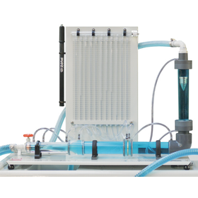
This is an experimental device for measuring pressure loss and flow measurement techniques in various pipes and fittings, consisting of a main body and a measuring manometer. Using three types of pathways that include measuring instruments, straight pipes, and bent pipe components, the characteristics of each component are investigated and compared using a manometer and a differential pressure gauge. In addition to learning general measurement methods and the application of Bernoulli's theorem, the experiment will compare pressure losses in a Venturi tube and an orifice plate, as well as determine the pressure loss in a sudden expansion pipe. The Pitot tube system within the device will derive the velocity distribution and flow coefficient in the transparent pipe cross-section direction. The experiment requires a H1F hydraulic bench (sold separately) for water supply and flow measurement.
Added to bookmarks
Bookmarks listBookmark has been removed
Bookmarks listYou can't add any more bookmarks
By registering as a member, you can increase the number of bookmarks you can save and organize them with labels.
Free membership registration
This is an experimental apparatus for visualizing flows similar to potential flow, which creates flow patterns using colored water to observe the flow around various shapes. Additionally, the four valves can control two water supply holes and two drainage holes located near the center to create streamlines. *It is recommended to supply water to the apparatus from a stable source such as an elevated tank.
Added to bookmarks
Bookmarks listBookmark has been removed
Bookmarks listYou can't add any more bookmarks
By registering as a member, you can increase the number of bookmarks you can save and organize them with labels.
Free membership registration
The friction loss of a horizontal small-diameter pipe (φ3xL524mm) will be measured, and the determination of the critical flow transition point and critical Reynolds number will be conducted through the ranges of laminar and turbulent flow. In the low flow experiments, an elevated tank and manometer will be used, while in the high flow experiments, the water supply pipe will be directly connected to the apparatus, and the differential pressure will be measured using a digital differential pressure gauge. The flow rate will be controlled by a needle valve at the downstream end of the test pipe, and water will be supplied using an H1F hydraulic bench (sold separately), although existing water supplies can also be used.
Added to bookmarks
Bookmarks listBookmark has been removed
Bookmarks listYou can't add any more bookmarks
By registering as a member, you can increase the number of bookmarks you can save and organize them with labels.
Free membership registration
This is an experimental device for understanding the significance of water hammer and cavitation that occur in pumps and hydraulic turbine systems. It consists of a 61-meter long coiled copper pipe, a solenoid valve, pressure sensors and Bourdon tube pressure gauges, a floating flow meter, a flow control valve, and a bypass valve. Water is supplied to a copper pipe with an inner diameter of 12.7 mm, and the flow rate inside the pipe is adjusted using the flow meter and bypass valve. The control box has a solenoid valve operation switch and a BNC terminal for pressure measurement, which can be connected to an oscilloscope (sold separately) to observe the behavior.
Added to bookmarks
Bookmarks listBookmark has been removed
Bookmarks listYou can't add any more bookmarks
By registering as a member, you can increase the number of bookmarks you can save and organize them with labels.
Free membership registration
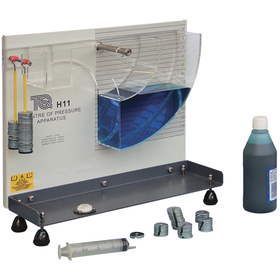
We will conduct experiments on the total water pressure acting on the flat and curved surfaces of a transparent plastic container with a quarter-circle shape supported by a fulcrum, as well as its points of action. We will fill the entire container or part of it with water and measure the forces exerted by the liquid, comparing them to theoretical values.
Added to bookmarks
Bookmarks listBookmark has been removed
Bookmarks listYou can't add any more bookmarks
By registering as a member, you can increase the number of bookmarks you can save and organize them with labels.
Free membership registration
We will conduct characteristic experiments on various flow meters used around us. The inlet and outlet of the piping will measure the pressure loss of the flow meter, and the flow rate will be calculated from the pressure difference, flow coefficient, viscosity, density, etc., of each flow meter. By comparing the experiments of each flow meter, we will understand the accuracy and characteristics of the flow meters and consider their usage. A nozzle-type flow meter is included, but other options (sold separately) such as a Pitot tube flow meter (H40a), a Venturi flow meter (H40b), and an orifice flow meter (H40c) are available. The experiment requires an H1F hydraulic bench (sold separately) for water supply and flow measurement.
Added to bookmarks
Bookmarks listBookmark has been removed
Bookmarks listYou can't add any more bookmarks
By registering as a member, you can increase the number of bookmarks you can save and organize them with labels.
Free membership registration
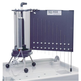
Measure the pressure distribution at a total of 11 locations along a horizontal semi-transparent Venturi tube, derive the theoretical flow rate using Bernoulli's theorem from each cross-sectional area, and calculate the flow coefficient from different flow rates (maximum flow rate of 27 L/min). The 11 manometer tubes are connected to the upper head, allowing for adjustment of the manometer water head level by operating the air valve. The experiment requires an H1F hydraulic bench (sold separately) for water supply and flow measurement.
Added to bookmarks
Bookmarks listBookmark has been removed
Bookmarks listYou can't add any more bookmarks
By registering as a member, you can increase the number of bookmarks you can save and organize them with labels.
Free membership registration
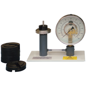
Calibration of the Bourdon tube pressure gauge will be performed using weights. A skeleton-type Bourdon tube pressure gauge is used so that the internal operation can be learned, allowing observation of the internal tube moving under pressure.
Added to bookmarks
Bookmarks listBookmark has been removed
Bookmarks listYou can't add any more bookmarks
By registering as a member, you can increase the number of bookmarks you can save and organize them with labels.
Free membership registration
This is a device for extensively experimenting with the operational characteristics of a centrifugal pump. It operates a pump with an internal observation capability using a variable speed motor, drawing water from a tank and circulating it back to the tank through a strainer, valve, and venturi tube. The impeller section is designed with a transparent cover for observation. The pump's rotational speed (rev/min), torque (N.m), output (W), differential pressure in the venturi tube (△P), and inlet and outlet pressures of the pump are digitally displayed, allowing for a wide range of experiments by changing operating conditions through valve adjustments. Additionally, by utilizing the optional data automatic collection system VDAS (sold separately), various data can be collected and analyzed in real-time on a PC (sold separately).
Added to bookmarks
Bookmarks listBookmark has been removed
Bookmarks listYou can't add any more bookmarks
By registering as a member, you can increase the number of bookmarks you can save and organize them with labels.
Free membership registration
This is a device for extensively experimenting and researching the operational characteristics of centrifugal pumps and turbines (water wheels). A variable speed motor operates the pump, drawing water from a tank and circulating it back to the tank through a strainer, valve, and venturi tube. The pump's rotational speed (rev/min), torque (N.m), output (W), differential pressure across the venturi tube (△P), and inlet/outlet pressure of the pump are digitally displayed, allowing for a wide range of experiments by changing the operating conditions through adjustments to the pump's inlet and outlet valves. By installing one of the separately sold options, such as a Pelton turbine, Francis turbine, or propeller turbine, along with a turbine dynamometer (MFP101a), it is also possible to measure the turbine's rotational speed, shaft torque, and output. Additionally, by utilizing the optional data automatic collection system VDAS (sold separately), various data can be collected and analyzed in real-time on a PC (sold separately).
Added to bookmarks
Bookmarks listBookmark has been removed
Bookmarks listYou can't add any more bookmarks
By registering as a member, you can increase the number of bookmarks you can save and organize them with labels.
Free membership registration
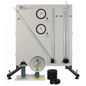
This is an experimental device for comparing and verifying differences in pressure measurement methods. The manometer setup, consisting of a vertical manometer, an inclined manometer, a pressure gauge, and a vacuum pressure gauge, will conduct comparisons of each measurement value and characteristic experiments. Additionally, a specially designed Bourdon tube pressure gauge allows for observation of the movement within the instrument's tube, and characteristic experiments will be conducted during pressurization and depressurization using weights. Each gauge and manometer has a pressure socket, and it comes with a T-joint and tube for conducting pressurization and vacuum experiments using a syringe.
Added to bookmarks
Bookmarks listBookmark has been removed
Bookmarks listYou can't add any more bookmarks
By registering as a member, you can increase the number of bookmarks you can save and organize them with labels.
Free membership registration
This is a device for conducting experiments on pressure and flow measurement in a Venturi tube, orifice plate, and floating flow meter, demonstrating the application of the energy equation (Bernoulli) for steady flow. The piping is made of transparent resin to allow observation of internal conditions, and measurements include the loss head caused by each flow meter, as well as the loss head from sudden expansions and 90° elbows. The experiment requires a H1F hydraulic bench for water supply and flow measurement (sold separately).
Added to bookmarks
Bookmarks listBookmark has been removed
Bookmarks listYou can't add any more bookmarks
By registering as a member, you can increase the number of bookmarks you can save and organize them with labels.
Free membership registration
We will experiment with the operation characteristics of two centrifugal pumps in series and parallel operation, or the performance of a single pump. The equipment consists of electric motors (constant speed) that drive each pump individually, a transparent acrylic water storage tank and valves, and a floating flow meter, with pressure gauges placed at the pump inlet and outlet. The impeller part of each pump is designed with a transparent cover for observation, and cavitation demonstrations can also be conducted. *There is also a PC data collection system type available with an experimental setup similar to H52. H53V Series and Parallel Pump Experimental Equipment (Variable Speed) H53V allows for variable speed control of the pump motor, displaying rotational speed (rpm), torque (N.m), power (W), pressure (bar), flow rate (L/s), and temperature digitally. Additionally, the accompanying software enables real-time data collection and analysis on a PC (sold separately).
Added to bookmarks
Bookmarks listBookmark has been removed
Bookmarks listYou can't add any more bookmarks
By registering as a member, you can increase the number of bookmarks you can save and organize them with labels.
Free membership registration
An oil pump used to move a liquid of a certain volume, which can be of rotary or piston type, is utilized in many industrial products such as lubrication systems, hydraulic systems, automobiles, and medical devices. It consists of a pump drive motor and control unit (MFP100), an oil tank, and a constant volume flow meter, measuring and digitally displaying the pump inlet and outlet pressure, flow rate, oil temperature, pump shaft speed, torque, and output on the control unit. Additionally, by using the optional data automatic collection system VDAS (sold separately), various data can be collected and analyzed in real-time on a PC (sold separately).
Added to bookmarks
Bookmarks listBookmark has been removed
Bookmarks listYou can't add any more bookmarks
By registering as a member, you can increase the number of bookmarks you can save and organize them with labels.
Free membership registration
This is a device used to experiment and research the operating characteristics of one or two spiral pumps (connected in series or parallel) over a wide range. Two variable-speed motors operate each pump, which can be observed internally, drawing water from a tank and circulating it back to the tank through a strainer, valve, and venturi tube. The impeller section is designed with a transparent cover for observation. The pump's rotational speed (rev/min), torque (N.m), output (W), pressure differential in the venturi tube (△P), and inlet/outlet pressure of the pump are digitally displayed, allowing for a wide range of experiments by changing operating conditions through valve adjustments. Additionally, by utilizing the optional data automatic collection system VDAS (sold separately), various data can be collected and analyzed in real-time on a PC (sold separately).
Added to bookmarks
Bookmarks listBookmark has been removed
Bookmarks listYou can't add any more bookmarks
By registering as a member, you can increase the number of bookmarks you can save and organize them with labels.
Free membership registration
This is a device for efficiently experimenting with the causes and phenomena of cavitation generated by pumps and turbines. The device consists of a water tank, an electric pump, a flow control valve, a flow meter, a pressure gauge upstream of the Venturi tube and a pressure gauge at the throat, and a Venturi tube (with a transparent window). It allows for easy observation of the occurrence of cavitation while adjusting the flow rate, helping to understand how cavitation begins based on the theory calculated from the temperature, density, and pressure of the water and experimental results.
Added to bookmarks
Bookmarks listBookmark has been removed
Bookmarks listYou can't add any more bookmarks
By registering as a member, you can increase the number of bookmarks you can save and organize them with labels.
Free membership registration
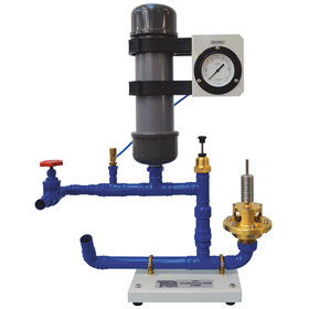
It is a pump that takes in water from a high position and transports it to an even higher position, known as a water hammer or water impact pump. It consists of a drainage valve, air tank, pressure gauge, flow control valve, and elevated water tank set, and is used for experiments in combination with the H1F hydraulic bench (sold separately) and others.
Added to bookmarks
Bookmarks listBookmark has been removed
Bookmarks listYou can't add any more bookmarks
By registering as a member, you can increase the number of bookmarks you can save and organize them with labels.
Free membership registration
This is a water wheel that uses the impact of water ejected from a nozzle as rotational force, consisting of an 80mm runner, an ejection nozzle, a friction load device (spring scale type), and an inflow pressure gauge. Experiments will be conducted while varying the ejected water volume and load. The device will be placed on a hydraulic bench (sold separately) for the experiments.
Added to bookmarks
Bookmarks listBookmark has been removed
Bookmarks listYou can't add any more bookmarks
By registering as a member, you can increase the number of bookmarks you can save and organize them with labels.
Free membership registration
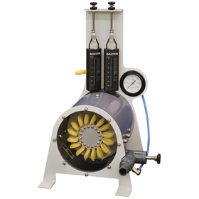
It is a water wheel that uses the reaction of water hitting the runner as rotational force, consisting of an 80mm runner (with 10 blades), 6 adjustable guide vanes, a friction load device (spring scale type), and an inflow pressure gauge, and experiments will be conducted while varying the inflow water volume and load.
Added to bookmarks
Bookmarks listBookmark has been removed
Bookmarks listYou can't add any more bookmarks
By registering as a member, you can increase the number of bookmarks you can save and organize them with labels.
Free membership registration
We will conduct experiments on the pressure loss of various piping used in residential central heating systems. There are straight pipes, bent pipes, and two pathways with valves and expansion and contraction mechanisms, and we will close the valve of one pathway to conduct individual experiments. The experiments will require an H1F hydraulic bench (sold separately) for water supply and flow measurement.
Added to bookmarks
Bookmarks listBookmark has been removed
Bookmarks listYou can't add any more bookmarks
By registering as a member, you can increase the number of bookmarks you can save and organize them with labels.
Free membership registration
A compact tabletop experimental device that compares the energy losses of three types of bent pipes, sudden expansion, and contraction pipes, consisting of a multi-tube manometer and a flow control valve. The experiment requires an H1F hydraulic bench (sold separately) for water supply and flow measurement.
Added to bookmarks
Bookmarks listBookmark has been removed
Bookmarks listYou can't add any more bookmarks
By registering as a member, you can increase the number of bookmarks you can save and organize them with labels.
Free membership registration
This is an experimental setup consisting of a shallow water tank and a floating pontoon (ark). By changing the height of the center of gravity and the angle of inclination, we analyze the shapes to derive stability.
Added to bookmarks
Bookmarks listBookmark has been removed
Bookmarks listYou can't add any more bookmarks
By registering as a member, you can increase the number of bookmarks you can save and organize them with labels.
Free membership registration